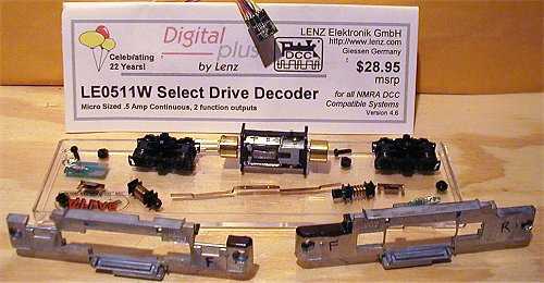
This locomotive comes with the newer slow speed motor, white LED's, and no provision for a DCC decoder. With a few common modeler tools, steady hands, good eyes, and soldering skills you can fit the Lenz LE0511W decoder inside.
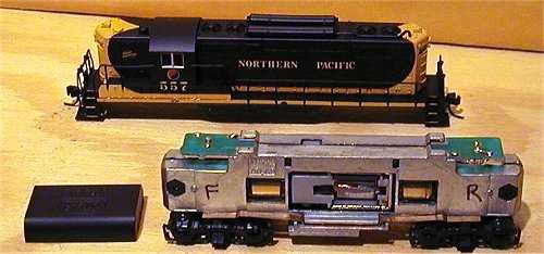
Start by prying the fuel tank off with a jewelers screwdriver.
Next slide the shell off the frame by holding the frame at the fuel tank and shell under the torpedo tubes and pull. It slides off very easy. Remove the electrical pickup strips.
Mark the frame Front and Rear. Also mark the bottom of the trucks F and R with an arrow pointing the direction of drive so you can replace them exactly later.
Next disassemble by removing the 2 frame screws, then using a very small jewelers screwdriver push the 8 plastic motor cradle tabs in.
Starting with the top 2 tabs, push down then in and spread the frame halves apart. Hold that position and repeat with the bottom 2 tabs. The trucks should fall out now. Carefully spread the frame halves apart exposing the mechanism. Remove parts and orient them in order so they can be replaced exactly later.
To get the motor out you need to finish removing the cradle by pushing the remaining 4 tabs as above. Remember to mark the motor Top and Bottom sides for proper replacement.
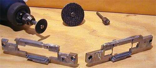
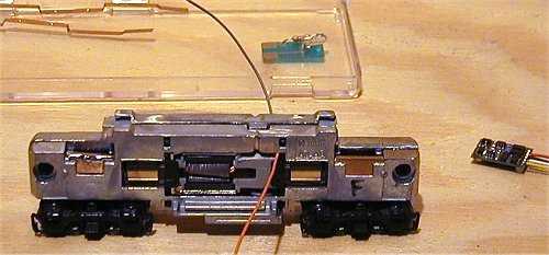
I marked the frame where material needs to be removed with a black sharpie pen.
I used my motor tool to grind away all the marked area for the decoder to fit. You can use a hack saw, bench grinder, or a belt sander as available to do this. I also cut a groove on each side just behind the motor cradle tab holes for the motor wires to fit.
The photo of the motor with wires soldered on did not come out, but I cut the brass strip for motor contacts just small enough to solder the wires on.
The Orange wire goes to the top and the gray wire to the bottom. I de-soldered the wires from the decoder for this. You can cut them for later splicing and leave 3/8" on the decoder if this type of micro-soldering is too difficult.
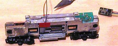
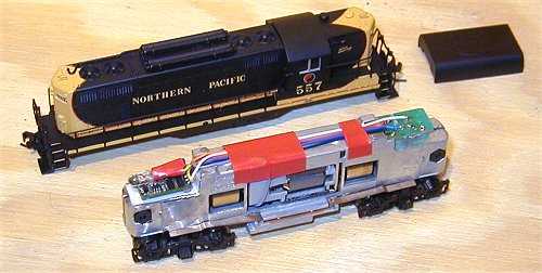
After soldering the wires on the motor I re-assembled the loco as shown. You can see the groove I cut in the frame for the motor wires just behind where the orange wire comes out.
I put tape to hold the motor wires in the groove. I also modified the light board for use as electrical pickup.
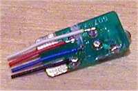
In the next photos you can see the modifications I made. In the left photo I cut the trace that goes the LED with an Exacto blade.
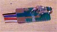
In the middle photo you can see where I drilled a small hole and moved the resistor lead through it. It was originally soldered through the top left hole.
The left photo also shows where each colored wire gets soldered to this board.
I used a piece of double sided carpet tape to hold the decoder in place and cut all wires to length. I soldered the motor wires directly to the decoder, but again you can choose to splice them if you had cut them to 3/8" as above.
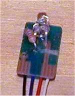
I de-soldered the LED and resistor from the other light board, and soldered the resister to the anode. (the + or small side of the LED)
The Blue wire connects to the resistor and the yellow wire connects to the LED cathode. (the - or big side of the LED)
Mine ran fine first try after programming, but these new slow speed motors need a higher starting voltage, and they don't seem to M.U. with older Atlas loco's