I found a way to fit a decoder in this loco without using a Dremel tool. As you know this model has given fits to decoder installers because of the limited space in the narrow body, and my first install on one of these models using a Dremel left me with a model that does not run so smooth. This one glides like it's on ice. The secret is:
1) Mark your frame, trucks, and parts, and replace them in the exact order of removal.
2) Be extremely gentle on the frame and do not bend it. Hold it as though it were made of glass.
Install Notes:
Soldering Iron:
I used a 25 Watt setting, and I soldered to the flexible strip that connects the motor brushes to the frame halves. It is recommended that you remove these before soldering, to avoid melting the motor brushes out of the motor.
Wiring Color Codes:
It was brought to my attention that I may have the Orange and Gray wires swapped, as well as the Red and Black. It works perfectly, wired as shown but it should be noted:
Lenz instructions don't say top or bottom of the motor. They always say
"Orange wire to where the right rail was and Gray to where the left rail was previously connected"
You can see where the confusion came from. They don't specify
which rail is right or left.
Do you look at the locomotive from the top or from the front as it comes towards you?
Digtrax rules are that:
The RED wire goes to right-hand side/ right rail/ engineer's side.
The BLACK goes to the left-hand side / left rail / fireman's side.
The GRAY goes to the Motor -ve
The ORANGE goes to the Motor +ve
BLUE is common.
WHITE is forward light
YELLOW is reverse light.
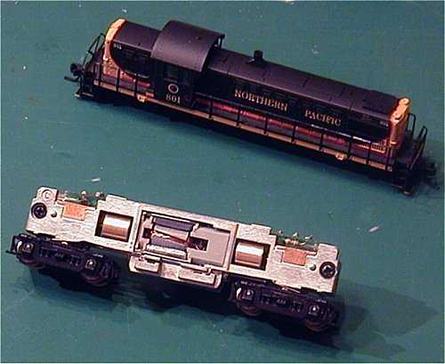
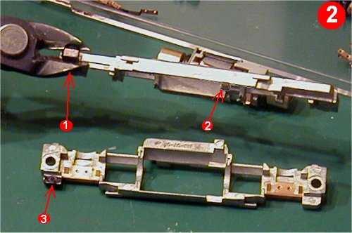
Disassembly of the locomotive is easy with newer Atlas releases. Just gently lift off the shell, remove the fuel tank cover, and you have access to a normal Atlas mechanism:
I marked the frame material that must be removed in black. 1 and 2 are the front LED centering nubs, and 3 is the motor frame to motor brush contact nub.
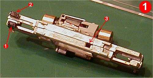
I just nipped the nubs off with my Rail Nippers, You might be able to use household wire cutters, but will probably need to carefully file a little material off. (don't bend the frame)
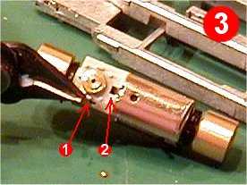
Cut the motor to frame contact strips off the motor as shown in Picture 3. Bubble #1 shows that I have left 2 millimeters of material to solder the motor wires to. Carefully tin the strips and rotate them on their brush holder shafts to point towards bubble #2.
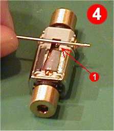
Picture 4 shows where you are going to melt an indentation for the lower motor wire. (Grey Decoder Wire) Notice bubble #1 points near the White Magnet. Only one side of the lower magnet is White. This is the side of the motor to melt the indentation.
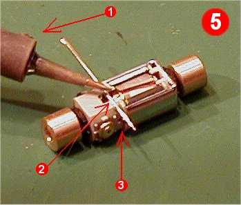
Picture 5, bubble #1 is the soldering iron. I used the #2 temperature setting, which corresponds to about a 25 Watt setting. Bubble #2 shows where the needle has slightly melted into the plastic. Do not melt too deep, just use the soldering iron tip to touch the needle in deep enough for a decoder wire. Bubble #3 shows that I have the needle placed over the points where the motor contact strips are.
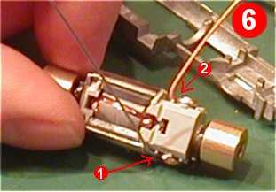
Picture 6, bubble #1and #2 just show where I soldered the motor wires. Notice the White Magnet. Remember this is the bottom, so the Grey wire goes closest to it. Also visible is the indentation we melted for the Gray wire.
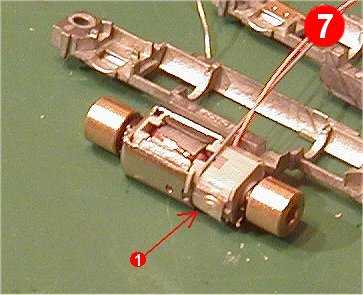
Picture 7, bubble #1 shows that I wrapped the motor in a thin strip of Scotch Tape, covering the brushes so they do not touch the frame. There is plenty of clearance, but I feel safer anyway.
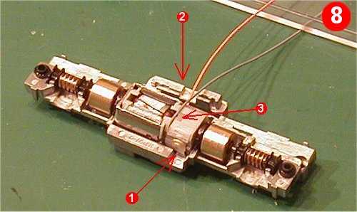
Here bubble #1 shows he clearance of the motor brush, and you can see it is close so the tape is probably a good idea. Bubble #2 shows where to route the motor wires, and at bubble #3 you can see the Gray wire sitting in its channel.
At this time put the mechanism back together in reverse order of disassembly.
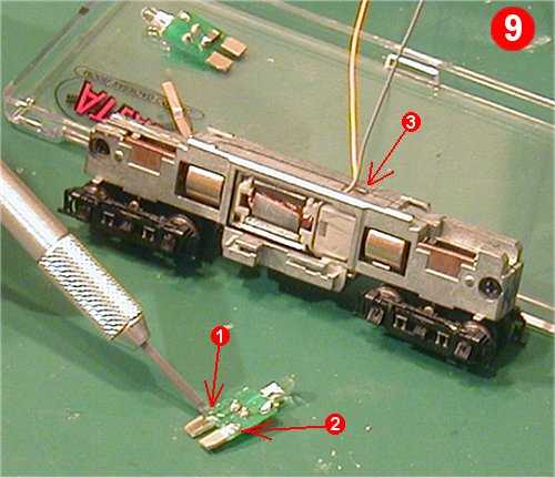
In this picture I have used a small chisel to cut the circuit traces from the Rear Light Board, bubbles #1 &2. The mechanism is assembled and bubble #3 shows where the motor wires come through.
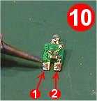
Picture 10 shows the front light board. It won't fit but I used the two tabs that press under the frame for electrical pickup. I melted a dab of solder on them to make them a little thicker for a tight fit where the front light board connected to the frame.
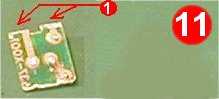
Picture 11 shows where I cut off the tabs after melting on the solder bumps. Not shown it that I pressed those tabs, solder side up, into the slots where the light board went. I also cut off the LED and Diode for use on the decoder.
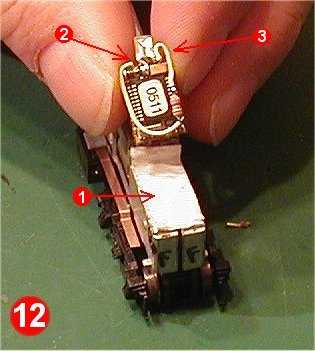
Picture 12, bubble#1 is thin Double Sticky Back Carpet Tape. I got it at K-Mart in their hardware section, but I have seen it at Home Depot and Ace too. Bubble #2 shows the + or Anode side of the LED. I bent the lead and carefully soldered it to the device that the Blue Wire is soldered to. Extreme care has to be taken to not short out the leads for the Yellow device, or you will pop your decoder. (The leads on the Yellow device go half way up the package, and I think it is the Bridge Rectifier, so Track power will be present)
Picture 12, bubble#3 is the White Forward LED wire. I spliced the resistor from the light board in series, and soldered to the - or Cathode side of the LED. (If you look inside the LED package you see the thin side is the + Anode and big side is the - Cathode)
Now you don't have to use the LED that came with the locomotive, you can order an SMD LED from Ngineering and it will fit better, but I'm cheap so I filed mine down to the smallest size possible without exposing any of the insides.
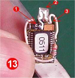
Picture 13 gives a better look at the front LED soldered to the decoder. 1 is the Anode soldered to where the Blue wire comes from, 2 is the filed down LED, and 3 is the white wire soldered to the Cathode.
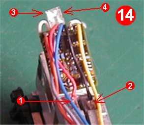
Picture 14 shows more decoder wiring. Point 1 is the Red wire connected to the left side of the frame, and 2 is the Black wire to the right side. They are soldered to the tabs I cut from the front light board. 3 and 4 are top views of the LED where you can see through the LED package and see the Cathode on the left and Anode on the right.
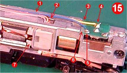
Picture 15 shows 1, Scotch Tape all the wires down to the frame. 2, the hole where we clipped the frame for the motor wires to pass through. 3 is the cut trace, 4 the Yellow wire gets soldered here, and 5, the blue wire gets soldered here. 6 is the other cut trace. As you can see the + Blue wire is in effect soldered to the resistor and the - Yellow wire is soldered to the Cathode
Bubble #7 shows how nice the Grey Motor Wire sits in it's channel.
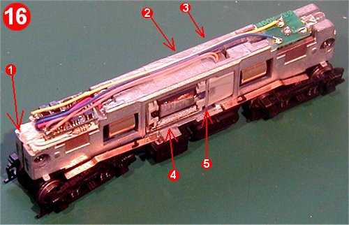
Picture 16 shows the completed wiring. At point 1 you can see the front LED is flush with the frame, Point 2 is the wires taped down, 3 is the motor wires coming out of the frame, 4 is the white magnet, and 5 is the gray motor wire sitting nice in its channel. The shell slides on easily and since their is no binding this loco runs very smooth and quiet.